 01
01High-volume
CNC machining
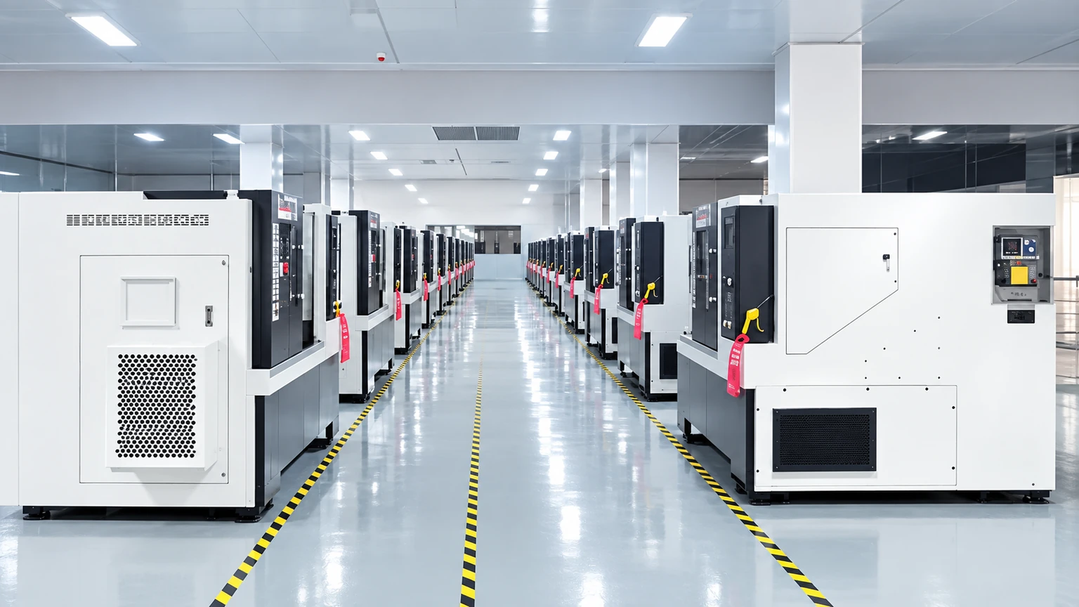
A base of 52 drilling and tapping machines supports repeat hole patterns, threaded features and batch production. Fixtures and inspection checkpoints are planned around each part family.
 GEOMETRIC
HIGH-CAPACITY PRECISION MANUFACTURING
Complex geometries. Repeatable production.
CNC machining, precision metal components and tooling for demanding industrial applications.
01 / MANUFACTURING CAPABILITIES
From a complex first part to a repeat production program, align the process with the geometry, material and application.
01A base of 52 drilling and tapping machines supports repeat hole patterns, threaded features and batch production. Fixtures and inspection checkpoints are planned around each part family.
 02
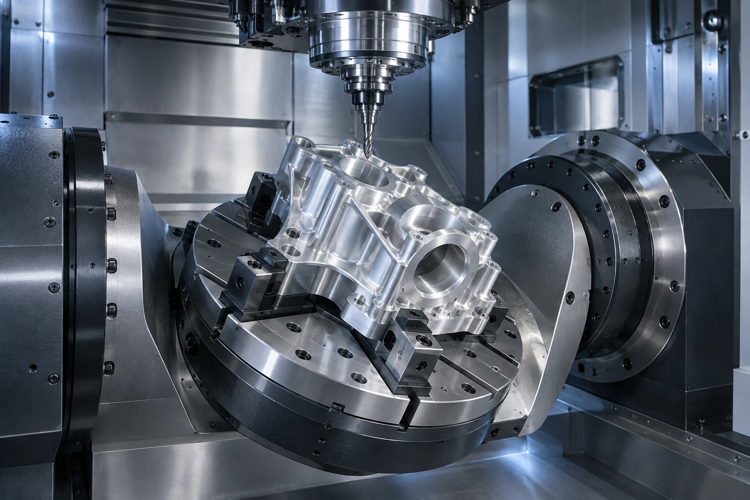
02Five 5-axis machining centers support complex contours and multi-face features, with careful attention to datums, tool access and setup strategy.
 03
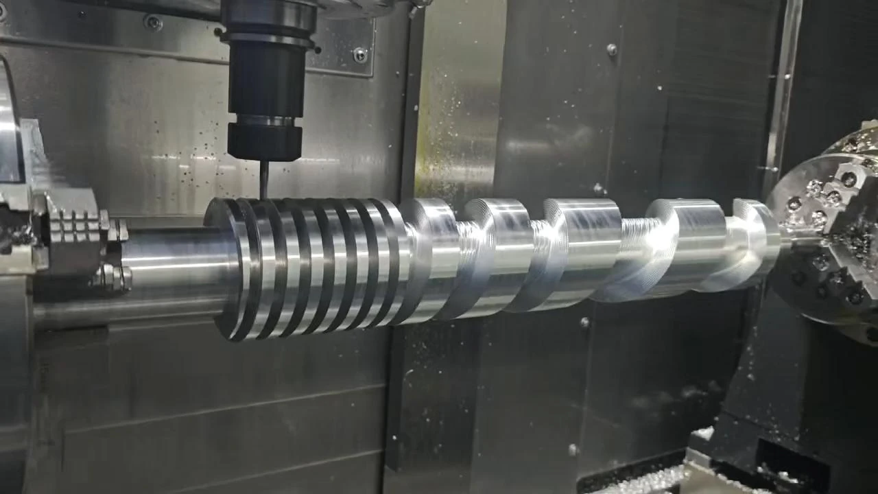
0324 turning machines, including 2 mill-turn machines, complement milling for shafts, fittings, housings and assembly interfaces manufactured to your drawings.
 04
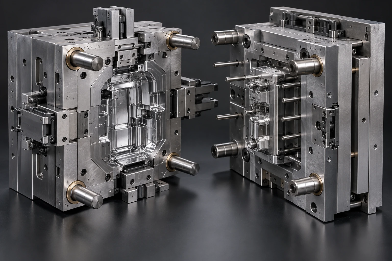
04Milling, wire EDM and 3 sinker EDM machines support mold cores, cavities and inserts, with grinding and mold trials connecting tooling manufacture to part approval.
02 / INSIDE THE WORKSHOP
Production equipment, organized work areas and dedicated inspection — a closer look at how parts move from machining to verification.
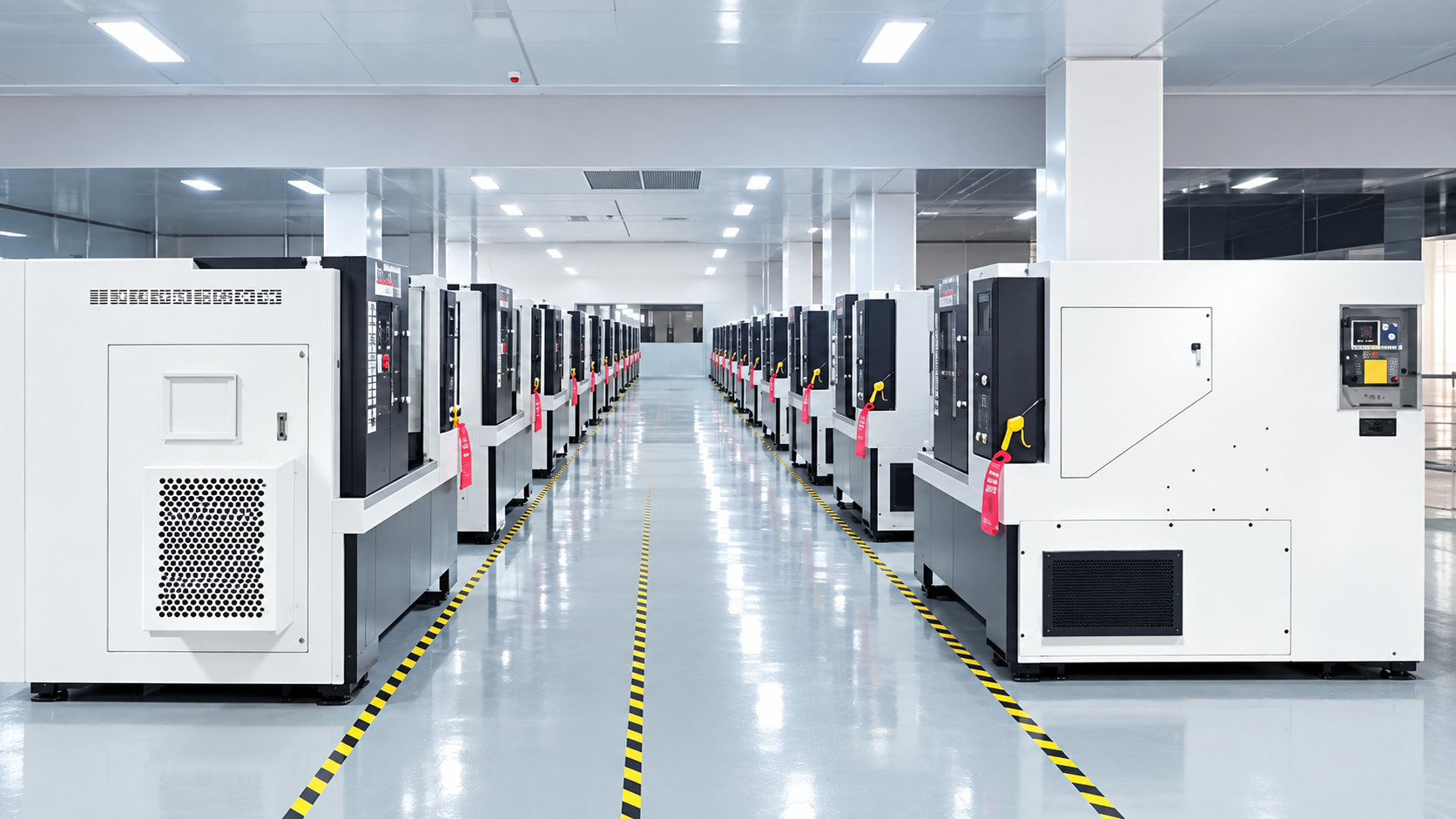
Our combined CNC equipment base exceeds 120 machines across drilling and tapping, milling, turning and engraving. This breadth supports process matching across part families, from initial samples to repeat programs. Machine allocation and delivery schedules are confirmed for each project.
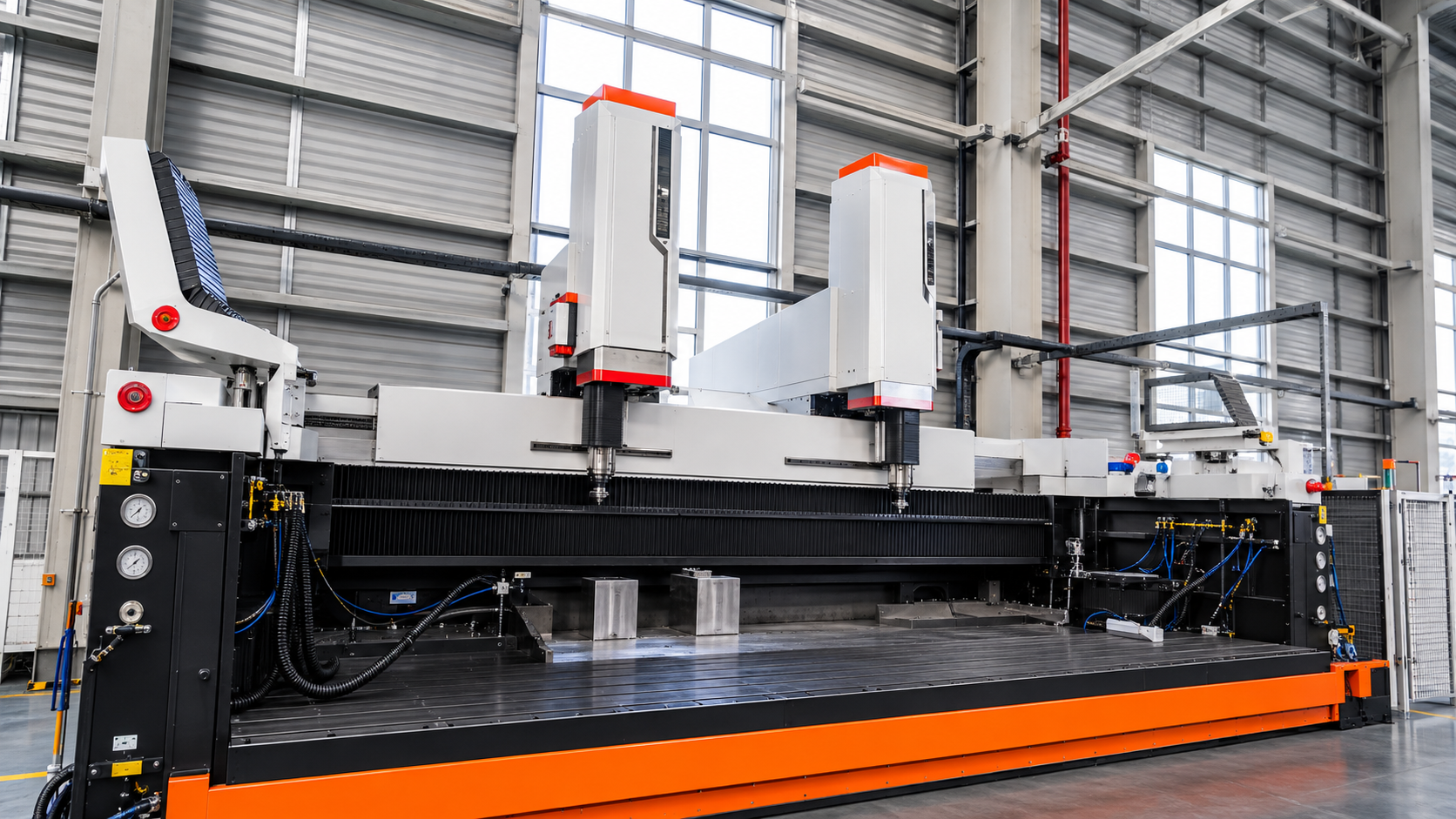
Three gantry milling machines complement the production fleet for larger plates, equipment structures and tooling. Working envelope, fixturing and process suitability are reviewed against each drawing.
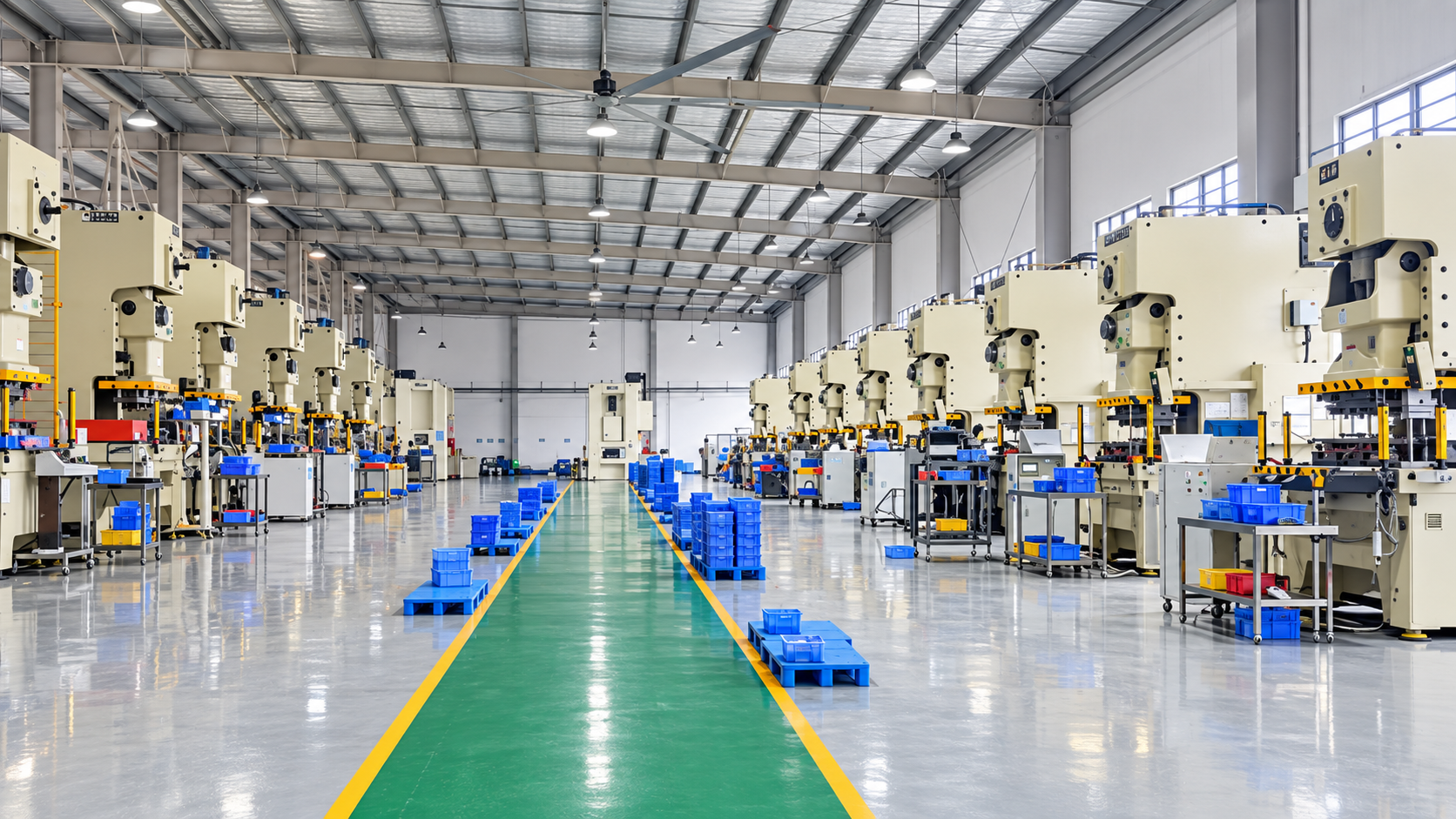
Seven mechanical presses complement CNC machining for stamped metal components. Die design, material thickness and forming requirements determine the appropriate production route.
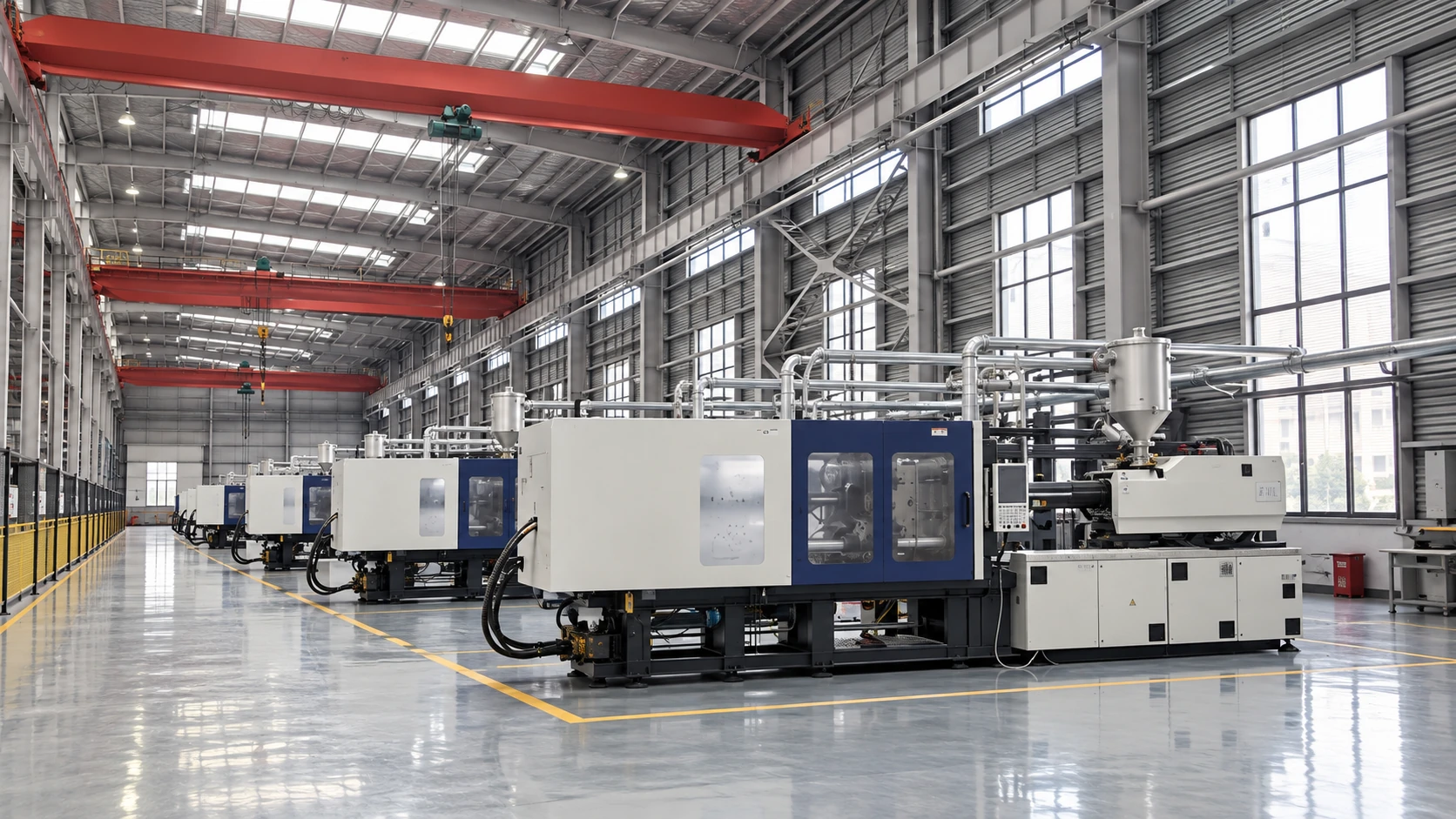
20 injection molding machines cover production and mold trials, with listed clamping capacities from 130 to 1,600 tonnes and two-color molding options. Material, mold setup and process conditions are reviewed around the component’s geometry and assembly fit.
03 / APPLICATION ENGINEERING
Start with the function of your part. Connect its geometry and interfaces to a practical manufacturing route.
Chamber components, precision housings, mounting plates and motion-system interfaces.
Example: multi-face equipment housing. Review mounting-face flatness, bore alignment and surface requirements, then plan setups and measurement against the drawing. Five-axis machining can reduce repeated repositioning for suitable geometries. Define cleanliness, traceability and protective packaging requirements during the RFQ.
Illustrative application, not a completed customer project.
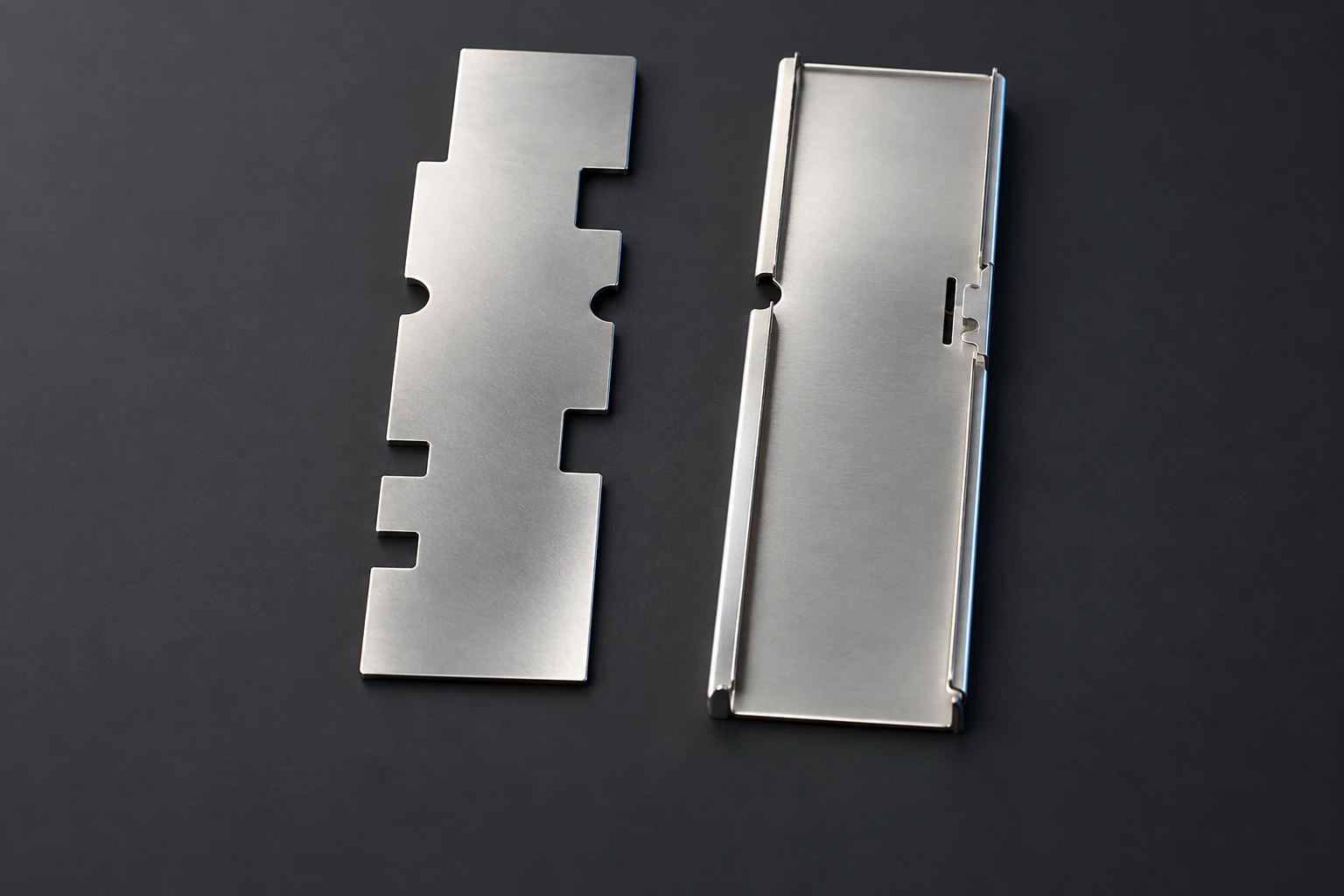
Custom brackets, mounting plates, locating features and precision metal housings.
Example: a precision mounting plate. Review the datum structure, mating surfaces and hole positions. Align material, finish and inspection requirements with the assembly before releasing repeat production.
Illustrative application, not a completed customer project.
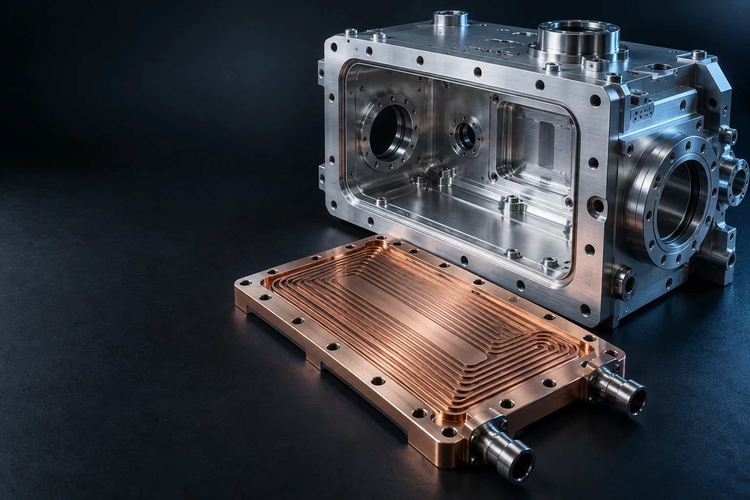
Machining enquiries for cold-plate bodies, manifold blocks and mounting interfaces, reviewed against your component drawing.
Example: a machined manifold block. Review port positions, threaded features, sealing surfaces and internal intersections. Use repeat fixturing and agreed inspection points to support batch consistency. Specify downstream joining, leak-test and cleanliness requirements in the RFQ.
Component machining scope is reviewed per drawing. Complete liquid-cooling systems are outside this offering.
04 / FROM DRAWING TO DELIVERY
A manufacturing conversation built around your drawing, your acceptance criteria and your production needs.
Share drawings, material, quantity and the features that matter to the application.
INPUT / PROJECT BRIEFAlign manufacturability, process options, inspection scope and commercial requirements.
OUTPUT / AGREED SCOPEAgree sample requirements and acceptance criteria before releasing a production program.
GATE / PART APPROVALAllocate machines and fixtures by part family, then plan repeat batches around approved drawings, agreed inspection points and available production time.
FOCUS / REPEATABILITYConfirm final documentation, protective packaging and shipment requirements.
OUTPUT / DELIVERY PACKAGE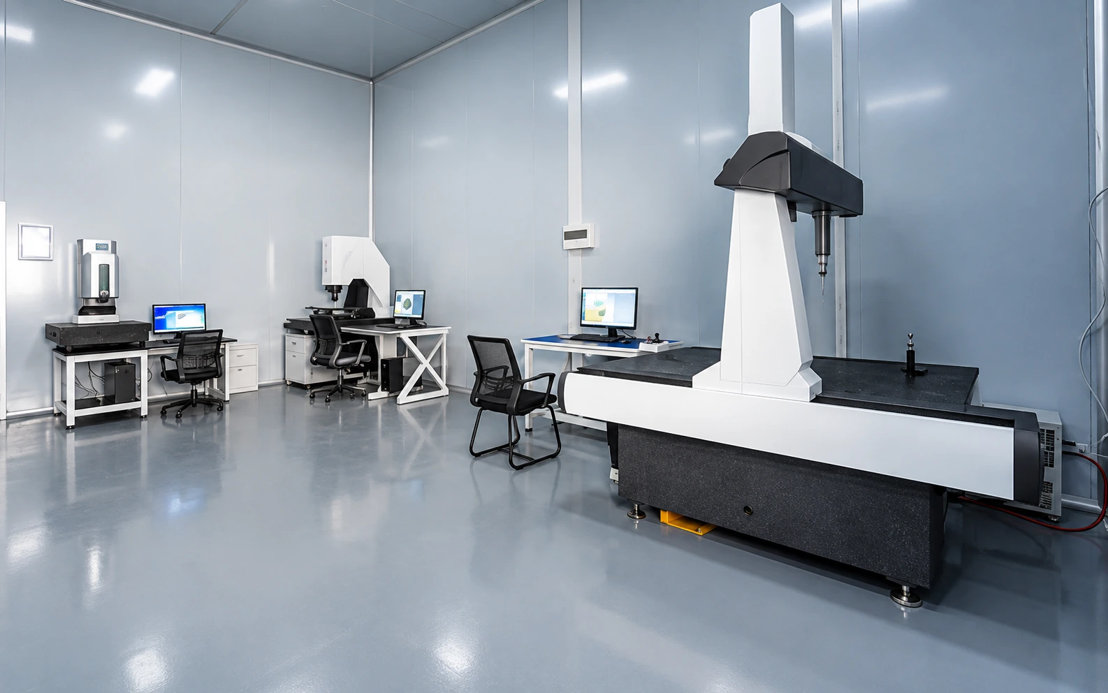
MEASUREMENT THROUGH THE PROCESS
Review critical dimensions with coordinate and optical measurement. Agree sample results and acceptance criteria before repeat production.
Complete the agreed final checks, review inspection documentation and confirm protective packaging before shipment.
05 / MEASUREMENT & QUALITY
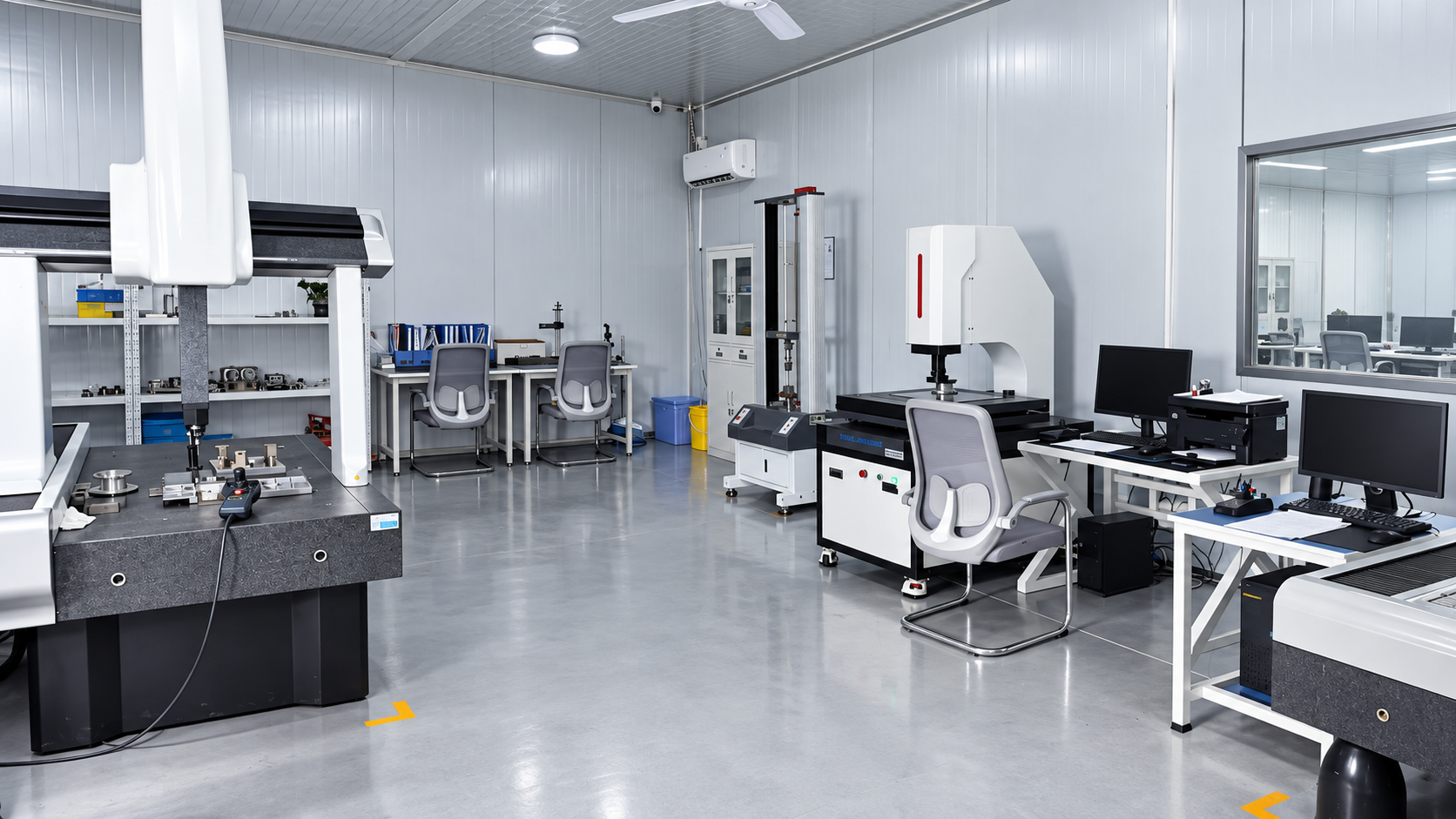
Coordinate measurement is complemented by 3 optical measuring systems: 2 automatic and 1 manual. Define critical dimensions, sampling and inspection records before production begins.
A bridge-type CMM uses a probe to measure spatial features and their relationship to the drawing’s datums.
Two automatic and one manual optical measuring system support checks of visible edges, profiles and small features against agreed inspection requirements.
Identify the governing drawing, datums, tolerances and critical-to-function features.
Specify the alloy or grade, surface treatment and any required supporting documentation.
Agree the measurement method, sampling scope and reporting requirements for your component.
Discuss surface condition, traceability, handling and packaging requirements for your component.
Tolerances, testing and documentation are confirmed per project during technical review.
GEOMETRIC TECH DYNAMICS
Geometric Tech Dynamics is a business division focused on high-capacity precision manufacturing: CNC machining, 5-axis precision machining, precision metal components and precision mold manufacturing.
We bring these disciplines together for engineering and sourcing teams developing semiconductor equipment, industrial automation, thermal-management components and precision tooling.
06 / START A TECHNICAL CONVERSATION
Tell us what you are building and what your component needs to do.
Alexa@gtd-supply.com ↗Attach your STEP file and 2D drawing to the email. Include the revision, material, finish, quantity and critical requirements.
Need an NDA first? Mention it in your inquiry before sharing confidential drawings.
BEFORE YOU SEND YOUR DRAWING
A 3D STEP model, a dimensioned 2D drawing with revision, material and finish specifications, quantities and target timing. Flag critical dimensions, inspection needs and packaging requirements.
Yes. Describe the intended function and which design decisions remain open. The inquiry can focus on geometry, process selection and the information needed for a detailed review.
They are reviewed against the actual geometry, material, quantity, finish and inspection scope. Include your targets in the inquiry so feasibility and timing can be evaluated for your project.
The application briefs show representative engineering considerations. They are not customer case studies. Equipment descriptions explain general functions; exact specifications are confirmed during project review.
This page does not store your form entries or upload files. The email option opens your email app, where you review and send the message. The copy option places the inquiry on your clipboard. Share confidential drawings only after agreeing the appropriate arrangements with GTD.